As it always goes with these large projects, I'd finally thought about the electrical system long enough, and done enough staring at wiring diagrams, to get in and have a go at the last of the really big modifications- the wiring harness.
The new engine and ECU needed a few connections from the Jaguar to be hooked up. The main ones were switched power to the ECU and ignition module/engine itself and a new starter circuit. I could've used the existing Jaguar starter circuit, but the Holden V8 has the starter on the other side of the engine bay and I didn't want to run wires across from the existing relay as it would've been messy. The stock Jaguar wiring harness on the RH side of the engine bay only seems to have run the starter, brake warning circuits, alternator and a few engine connections, which I think were oil pressure/ coolant etc.There was the big EFI harness but that's now gone. I think I can remove about 70% of the wires on that side of the engine bay now, it's all over on the LH side.
I'm also taking advantage of the Holden ECU to trigger cooling fans, the stock program turns the fans on at 91c, as determined by the engine coolant sensor in the Holden ECU system. This trigger point can be changed with a new tune if I ever desire to do that, which may happen in the future, long after the car is running and sorted out! The ECU can also command fans on with aircon compressor, but I will just wire that off the A/C compressor. Less wiring, less connections to go wrong and simpler.
So, I needed to provide four relays for the new systems. One for starter, one to power ECU, one for Ignition module (I could've piggybacked the EFI relay, but two separate circuits make things easier in the future) and another relay for a new dual cooling fan setup. I'm not going to reuse the Jaguar electric fan system, it only powers one smaller fan and the wiring is old, so new relay and power to the fans. I'm already running wiring so no big deal! Back of the new relay block:

Front of relay block, half finished:

There's also a fuse block going in next to the relays to take care of the power supplies for fans, ECU, ignition module and a couple of spare blocks for future expansion.
The sensor sub harness of the engine needed shortening a little, all wires were cut, soldered & heat shrinked so I could forget about those joints forever:

I also went out and bought a new battery a few days ago and dropped that into the cradle. It needed modifying of course. The bottom flange of the battery is designed to be bottom clamped and is just a little too wide for the battery tray. Some gentle trimming fixed that.
The fuel pump and it's relay are all wired up now and I have also run a 5 core cable up to the fuel pump/ rear battery area, one wire is the fuel pump trigger from the ECU and the other four are for any possible future expansion. Remember, I removed the complete Jaguar ECU and harness from the boot, so the only wiring past the rear seat now are tail lights, main power and fuel tank sender, so a few extra wires may be needed in the future. With the ECU triggering the fuel pump, I no longer need the Jaguar inertia switch as the ECU will only run the pump for two seconds after it loses an ignition signal, so no need for it for crash safety. More clumps of wires and relays I can remove from the car.

And the finished battery and fuel pump area. Ended up reasonably tidy, unfortunately that was the only place I could mount the pump. It has two rubber mounting points so should be pretty quiet. I might fashion a light plywood box for the battery and pump, depends how bad it looks with the rest of the boot finished. As I said before, all the fuel line is now E85 rated and 250psi line, should be no problems well into the future:
Went a little overboard with the earth straps, but as the XJS has a long cable run from the boot, I wanted to reduce resistance as much as possible. Plus, EFI engines like lots of earth points for consistent voltage for correct sensor readings etc. I have about 600 amps of ground strap capability, battery is only good for 540 amps, so covered for any corrosion in the future. There will also be another earth strap off the transmission extension housing for the transmission electrics, so well covered for earths!:

Two earth straps run from the firewall, one to a cylinder head, one to a bell housing bolt. The third runs from alternator bracket to LH front swaybar bracket. This ensures a good earth for both alternator and front lights.
It's getting a little crowded on the LH side firewall, but some conduit and tidying up will make it look better. Not that stock XJS wiring is particularly neat anyway! That brass hose elbow is the fuel return, I've run the steel lines up and away from the engine:

Of course, I have also decided to replace the headlight fuse block, like everyone else does. I looked at it, thought it would be OK, then once the new fuse block went in at the firewall, it looked terrible. Plus, all the plastic terminal covers were disintegrating in my fingers.
A quick video of the engine cranking over. Spins nice and fast, definitely no resistance in the system:
So for aesthetics, consistency and reliability, I got rid of the ancient corroded fuse block and replaced it:

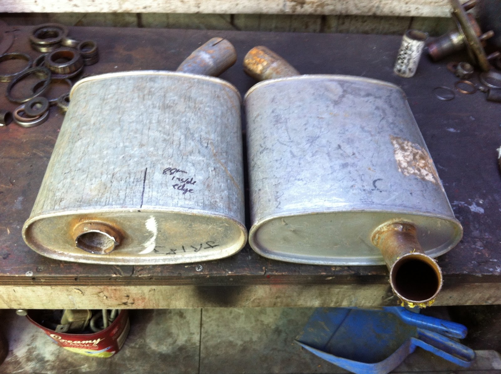
The exhaust is also slowly coming along. After searching for at least six months, I have realized there is a huge over supply of RH front muffflers, but LH mufflers are non existent. So, I bought another RH muffler from the same guy I bought the other one off and set about cutting the outlet off, flipping the muffler over and making it an LH muffler:

 It was actually a lot simpler than I anticipated. The OEM mufflers are good, heavily made units and galvanized as well. The engine pipes are also now in their final location and have flanges welded onto them, so I can now mount rear mufflers and cut the intermediate pipes to size and finish that off. The flanges and cats look like they hang a long way down. but they are no worse than factory. I'm not sure about having enough clearance for the flanges. If they hit in operation, I'll go to inline clamps or similar:


The shifter cable is also hooked up after some bracket making. This bracket simply bolts up to the back end of the transmission oil pan using two existing bolt holes and two longer bolts:

These photos aren't great, but you can sort of see the bracket in there:

And while I was there, a photo of the stock XJS right angle speedo adapter screwed right onto the TH700 transmission. It's great that GM kept everything standard across so many transmissions!

I still need to put a pulse generator for the ECU on there, but there's more than enough room there to do it now. I also have to run the three wires to the torque converter/ 4th gear/ trans temperature switches on the side of the gearbox and will make these and the speedo signal into a sub harness for ease of future maintenance. The trans temp sensor locks out 4th gear and overdrive when cold and also allows the ECU to "baby" the gearbox if the trans temp gets too high by unlocking the converter and dropping overdrive out. The ECU will also do all the locking and unlocking of the converter once it has the speedo signal, plus it will go into a lean cruise mode using the speedo signal. All in all, it's better to wire in the speedo signal than use an aftermarket switch as you get many driving benefits from the speedo signal, with just as many wires to hook up as using an aftermarket lock up converter kit.
Plenty more to do, stay tuned!
The new engine and ECU needed a few connections from the Jaguar to be hooked up. The main ones were switched power to the ECU and ignition module/engine itself and a new starter circuit. I could've used the existing Jaguar starter circuit, but the Holden V8 has the starter on the other side of the engine bay and I didn't want to run wires across from the existing relay as it would've been messy. The stock Jaguar wiring harness on the RH side of the engine bay only seems to have run the starter, brake warning circuits, alternator and a few engine connections, which I think were oil pressure/ coolant etc.There was the big EFI harness but that's now gone. I think I can remove about 70% of the wires on that side of the engine bay now, it's all over on the LH side.
I'm also taking advantage of the Holden ECU to trigger cooling fans, the stock program turns the fans on at 91c, as determined by the engine coolant sensor in the Holden ECU system. This trigger point can be changed with a new tune if I ever desire to do that, which may happen in the future, long after the car is running and sorted out! The ECU can also command fans on with aircon compressor, but I will just wire that off the A/C compressor. Less wiring, less connections to go wrong and simpler.
So, I needed to provide four relays for the new systems. One for starter, one to power ECU, one for Ignition module (I could've piggybacked the EFI relay, but two separate circuits make things easier in the future) and another relay for a new dual cooling fan setup. I'm not going to reuse the Jaguar electric fan system, it only powers one smaller fan and the wiring is old, so new relay and power to the fans. I'm already running wiring so no big deal! Back of the new relay block:


There's also a fuse block going in next to the relays to take care of the power supplies for fans, ECU, ignition module and a couple of spare blocks for future expansion.
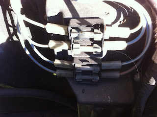
The sensor sub harness of the engine needed shortening a little, all wires were cut, soldered & heat shrinked so I could forget about those joints forever:

I also went out and bought a new battery a few days ago and dropped that into the cradle. It needed modifying of course. The bottom flange of the battery is designed to be bottom clamped and is just a little too wide for the battery tray. Some gentle trimming fixed that.
The fuel pump and it's relay are all wired up now and I have also run a 5 core cable up to the fuel pump/ rear battery area, one wire is the fuel pump trigger from the ECU and the other four are for any possible future expansion. Remember, I removed the complete Jaguar ECU and harness from the boot, so the only wiring past the rear seat now are tail lights, main power and fuel tank sender, so a few extra wires may be needed in the future. With the ECU triggering the fuel pump, I no longer need the Jaguar inertia switch as the ECU will only run the pump for two seconds after it loses an ignition signal, so no need for it for crash safety. More clumps of wires and relays I can remove from the car.

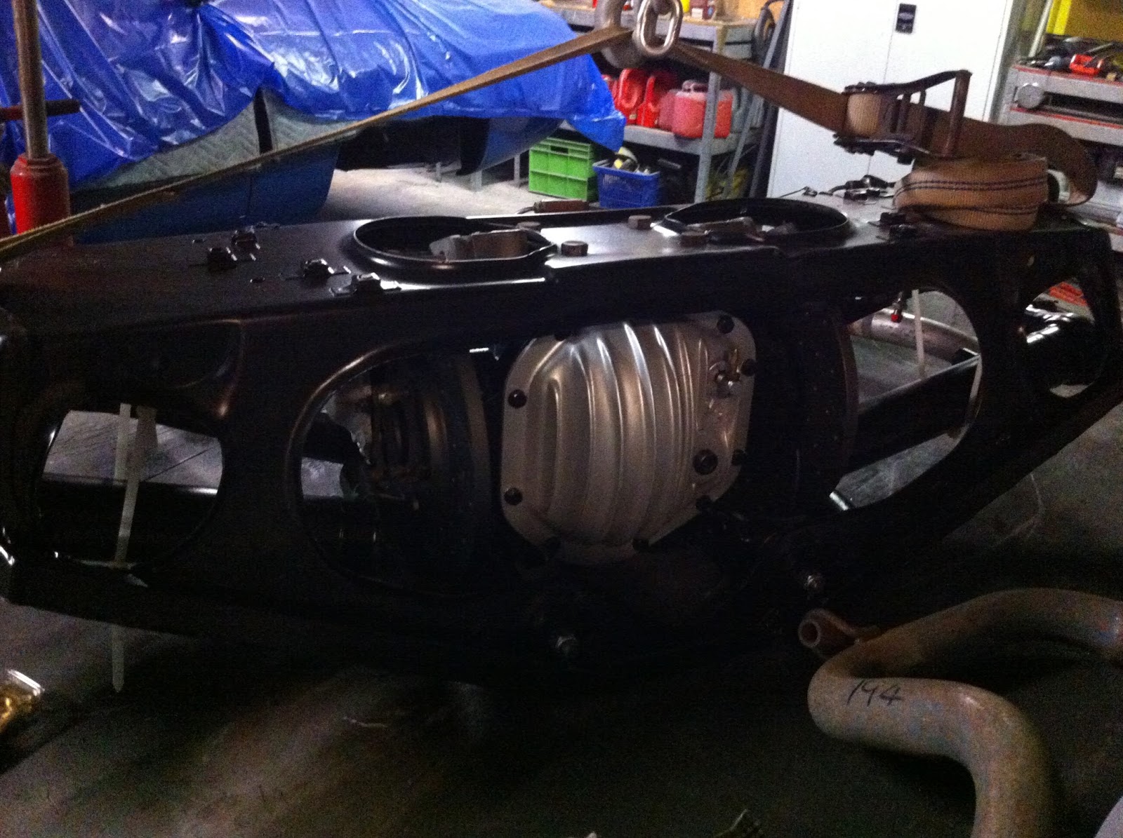
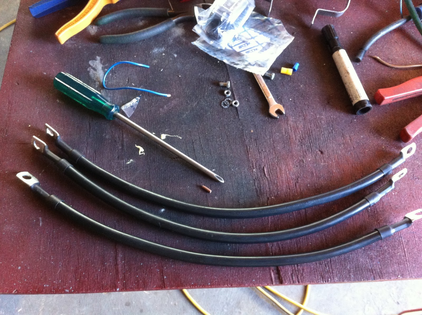
Went a little overboard with the earth straps, but as the XJS has a long cable run from the boot, I wanted to reduce resistance as much as possible. Plus, EFI engines like lots of earth points for consistent voltage for correct sensor readings etc. I have about 600 amps of ground strap capability, battery is only good for 540 amps, so covered for any corrosion in the future. There will also be another earth strap off the transmission extension housing for the transmission electrics, so well covered for earths!:
It's getting a little crowded on the LH side firewall, but some conduit and tidying up will make it look better. Not that stock XJS wiring is particularly neat anyway! That brass hose elbow is the fuel return, I've run the steel lines up and away from the engine:

Of course, I have also decided to replace the headlight fuse block, like everyone else does. I looked at it, thought it would be OK, then once the new fuse block went in at the firewall, it looked terrible. Plus, all the plastic terminal covers were disintegrating in my fingers.
A quick video of the engine cranking over. Spins nice and fast, definitely no resistance in the system:
So for aesthetics, consistency and reliability, I got rid of the ancient corroded fuse block and replaced it:


The shifter cable is also hooked up after some bracket making. This bracket simply bolts up to the back end of the transmission oil pan using two existing bolt holes and two longer bolts:


Plenty more to do, stay tuned!