The XJS has been the attention of plenty of work the last couple of months. I've even surprised myself with how much has been done. I've been getting smarter with ordering parts and ensuring a good lead time for them to arrive. I've also been setting things up so I have a few things on the go at once, so when parts arrive for one, I can keep going on that whilst I wait for other parts to arrive. Another little trick that has helped is trying to get a small task done one evening a week.
If you have ever disassembled a Jaguar IRS, you'll know there are a lot of sub assemblies that need to be reconditioned before you can start reassembly.
As you know in my last post, I had straightened and reinforced the rear suspension cage. Once that was done, it got thoroughly cleaned & painted in an epoxy mastic I bought from Rust Buster: http://www.rust.co.uk/epoxy-mastic-rust-proofing-paint/c28117/
It's pretty tough paint, but it is definitely not a coating I'd recommend to someone new to painting. Unthinned it is far too thick to flow well when brushing and when thinned enough to brush well, it has poor coverage.
However, it does spray very well with a gravity fed gun, but is very sensitive to being thinned just the right amount. I'd probably opt for their fuel tank coating if I wanted to paint anything I'd ever see regularly and wasn't hidden under the car.
Having said all that though, you can see the finish you can achieve is more than good enough for underneath a car!
Anyway, here are some photos of the painted cage and lower arms:

And here's a photo of the cage, lower arms and unpainted half shafts (minus the outboard ends, which are off so I can set bearing end float in hubs) You can also see the unpainted trailing arms top left of photo- they have had new bushes pressed in and just need paint:

My phone hasn't been coping well with high contrast and low light shots lately, so I apologize for some of these photos. Having the sun coming into the garage of an afternoon makes for lousy photos and I'm too impatient to wait to take photos of a morning!
Next up were the rear calipers. They got new pistons, seals & a coat of paint:

Of course, nothing on a 40 year old car is quite that simple! Some nice person before me had stripped out the threaded holes for the hand brake caliper pins on one caliper.After plenty of thinking, I bit the bullet & bought a UNF helicoil kit to repair them. I am absolutely sure I'll need more helicoils as I go along.
Helicoils are dead simple to use, I won't bore you with a how-to, there are plenty online, but here are some photos:

Helicoil assortment kit. The more helicoils you buy at once, the cheaper they become. I liked this kit as it included nice HSS drill bits and came in a steel case. I'll own it forever.
And the helicoils in their new home. I was initially concerned about getting the hole I had to drill for the helicoils dead straight, but the bottom hole the handbrake pivot pin sits in is quite oversize so is very forgiving of misalignment :

New stainless handbrake pins (with a little white lithium grease to ease assembly):

New springs and lock tabs:

Once that was done, it was on to the differential. The carrier bearings were fine, but the front pinion race had some light pitting, so I replaced it. Do not believe anyone online who tells you that it is easy to collapse a new collapsible spacer onto a pinion gear just using the nut to torque it down- it is IMPOSSIBLE! You need to put so much torque through the nut the levers become unworkably long & the thread just isn't designed for that. I used my press and it took a LOT of pressure to do it correctly.
Anyway, rant over!
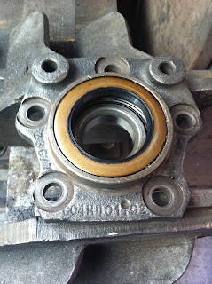
I also replaced the output shaft inner and outer bearings and seals. This is a straight forward job, but has a definite process needed so you don't end up backtracking.
First step is to drive out the bearing races out of the hub & drive new ones in:

Then drop the outer tapered roller bearing. Both inner and outer bearings are identical, so you can't get them wrong:

Install new seal. I coated my seals with a bit of aviation gasket as the bores were old and scored:

Then drive the seals in flush. It is important to get the seals flush as we don't want the seals to be too far out and riding on the radius of the output shafts-they'll leak if that happens:
Once that was done, we could install the output shaft into the outer bearing. here is the output shaft ready to go, a little grease on the seal area to prevent seal damage. I use a white lithium grease in a spray can, it's so easy to use and keeps everything including my hands nice and clean!:

Once that was done, we can press the output shaft into the outer bearing. I made a short video to demonstrate how easy the press makes things. Previously I would've been doing this in a vise with gigantic hammers and a lot of swearing, this makes it so much easier!:
Once that was done, it was a matter of dropping the new crush sleeve onto the shaft, then the new inner bearing:


Using the press, I then loaded the bearings and collar up until I got the right preload, then tightened the shaft nut from underneath the press. Simple, neat, no swearing and foolproof:

Job done:

I don't have any photos of assembling the lower arms into the cradle, but it's a tricky job. Not so much aligning everything, but getting the fulcrum shafts through everything as the friction builds up means you need to tap them in with a hammer and watch how everything is going.
I also decided to buy the bronze bushing kit for the lower arm pivot points from Classic Jaguar http://classicjaguar.com/cjparts/systembronze.php
As you can see, they are absolutely beautifully made and fit just as well as they look!

Don't worry- once you price up a kit for all new bearings, spacers and then work out the time needed to shim it all up, you'll end up realising these bushes are great value!
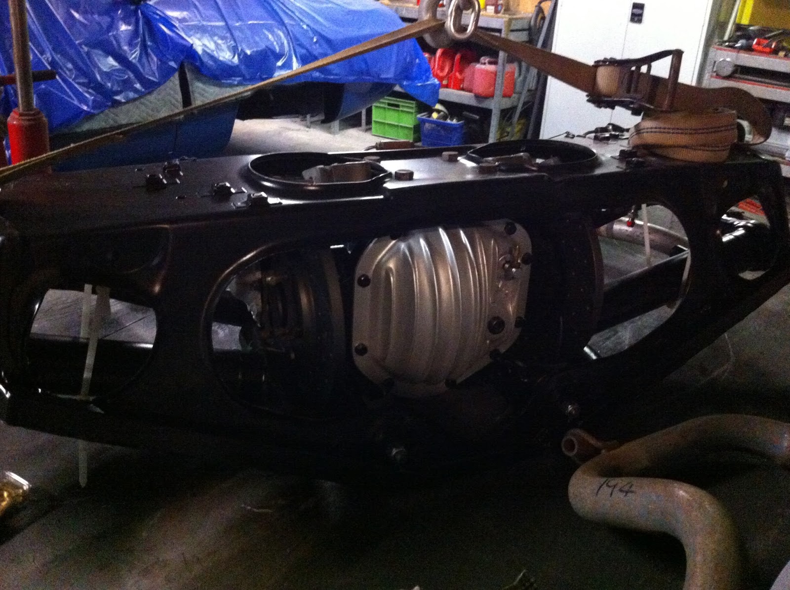
So, the rear suspension and differential, as of today, is at this point. Diff in, lower arms in, brakes done. All it needs now is for me to finish the outer hubs, then install the shocks and half shafts.I think I'll install the outer hubs and halfshafts in the car. It will make the rear end much lighter to handle and those parts are easily done on the car. I'll hang the shocks before the cage goes into the car though:

As you can see, I also splurged on an aluminium rear cover in the hopes
it'll keep the differential a bit cooler. This brand new piece was half
the price of what wreckers ask for used Jaguar alloy covers! It also has a much better breather setup, allowing me to run a hose off the cover into a loop, reducing the chances of oil blowing out as is common on Jaguar differentials:

I should also mention that one of the brand new handbrake pads I bought disbonded merely under the force of installing the brake calipers over the new rotors. They weren't even a tight fit at the time. So I had to buy new handbrake pads and install them in cage. You may wish to avoid Powauto handbrake pads....
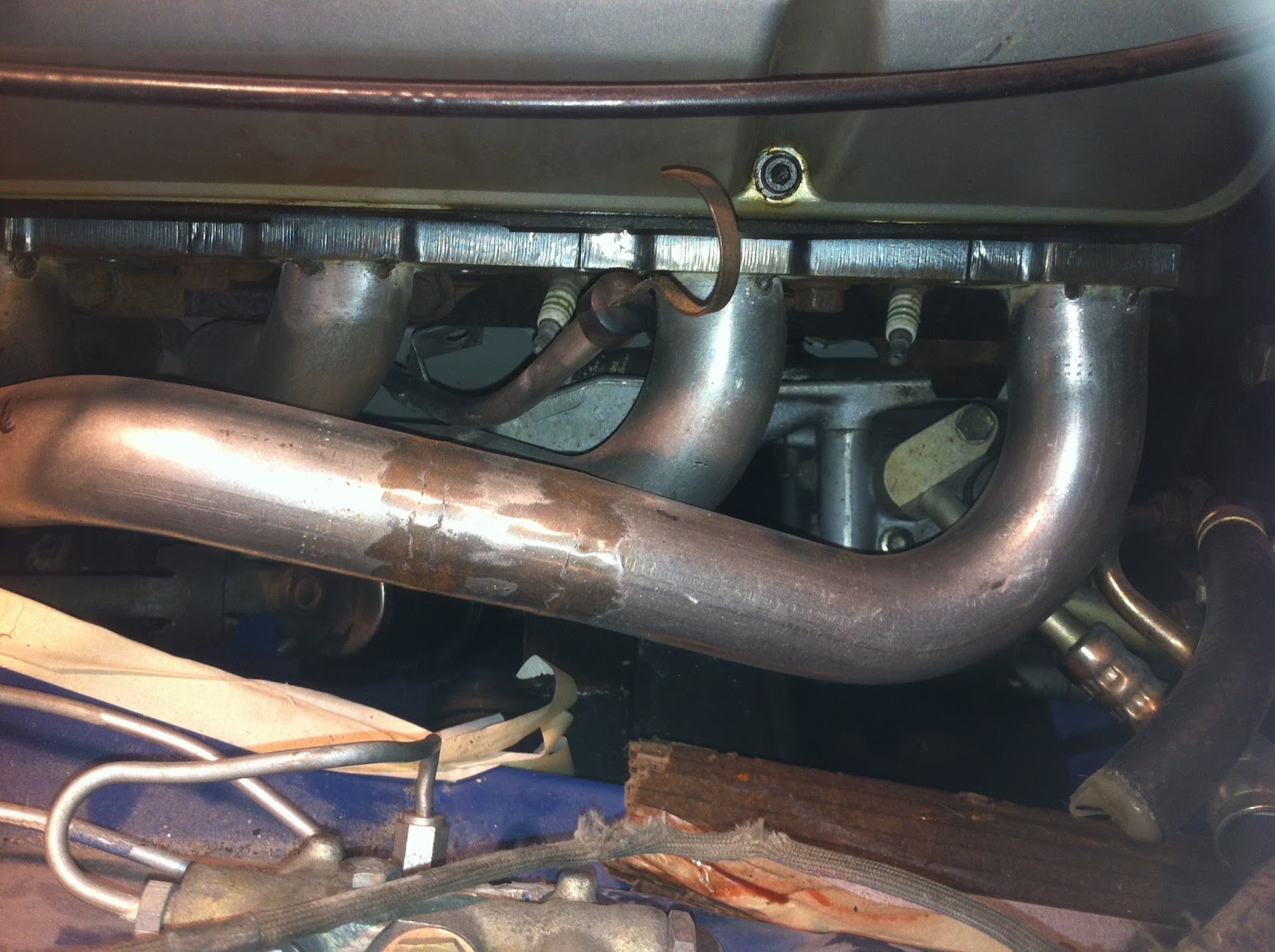
The fuel tank is also in and completely plumbed up with my E85 friendly lines:


A few things to note; that kinked inlet line to the pump has been replaced with a 180 degree AN fitting, the new pump is a Bosch 044 which was about the same price as a stock replacement, but offers much more scope for any future modifications, and a Bosch 044 will NO WAY fit in the stock pump location!
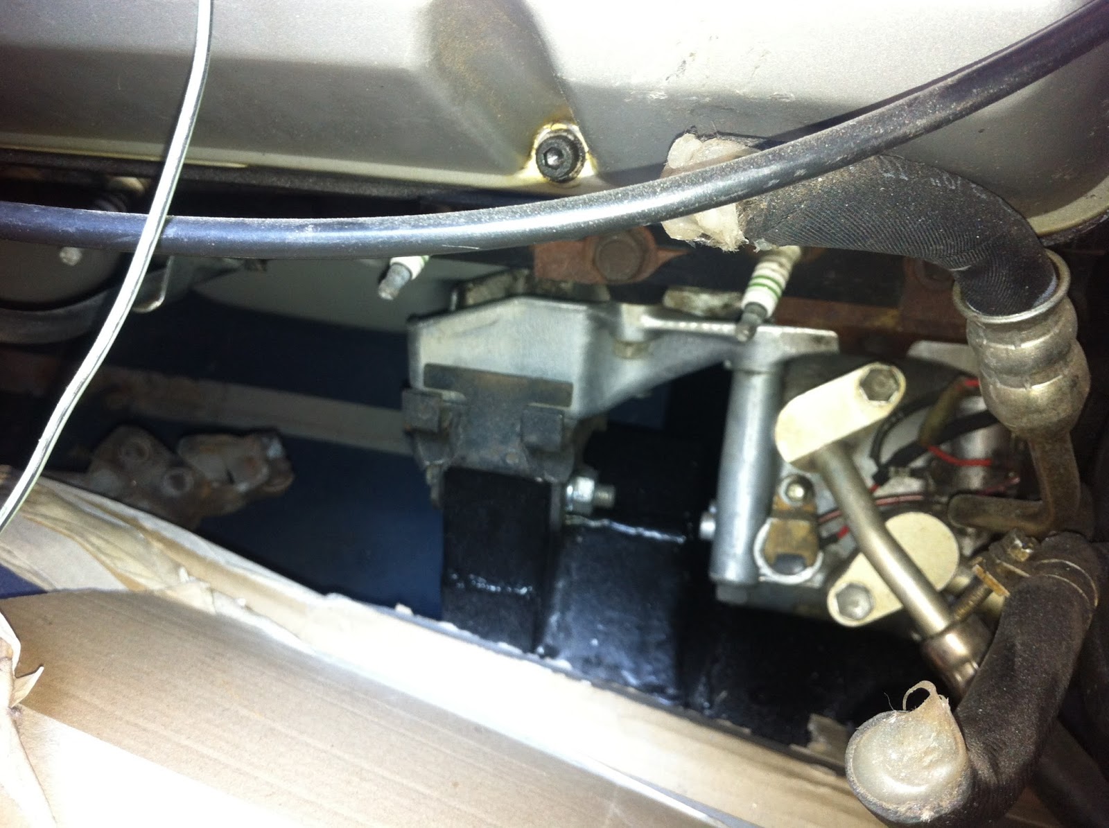
I made a simple bracket that hangs off the battery tray for the pump and it's a nice spot for it. Out of the way.
Also, the stock hard lines with rubber links in them can easily be converted to new rubber by simply cutting off the old band clamps, installing new hose and using proper EFI clamps. I didn't want to go to all the trouble of renewing the fuel system and have those tiny bits of 40 year old rubber be my undoing!
Rear brakes:
The rear caliper bolts are a royal pain to install and may well partially strip on you when installing them. I didn't need to do this, but the new aftermarket rotors you buy now have an access hole that aligns with the outboard end of the caliper bolts. When I need to remove the calipers in the future, I will drill out the threaded sockets for the caliper bolts in the output shaft carrier, install the bolts from the disc side through the caliper and put nuts on the inboard end.
It eliminates the threads in the output shaft carrier and means you only need to fit a nut inboard between diff housing and calipers, not a whole bolt!
I've also bought some new, stock replacement intermediate exhaust pipes for the car and have one new old stock over axle pipe and front muffler. I need to chase up a RH over axle pipe and a LH front muffler. I won't fit rear mufflers till I hear how loud the car is, it probably won't need them.
If you have ever disassembled a Jaguar IRS, you'll know there are a lot of sub assemblies that need to be reconditioned before you can start reassembly.
As you know in my last post, I had straightened and reinforced the rear suspension cage. Once that was done, it got thoroughly cleaned & painted in an epoxy mastic I bought from Rust Buster: http://www.rust.co.uk/epoxy-mastic-rust-proofing-paint/c28117/
It's pretty tough paint, but it is definitely not a coating I'd recommend to someone new to painting. Unthinned it is far too thick to flow well when brushing and when thinned enough to brush well, it has poor coverage.
However, it does spray very well with a gravity fed gun, but is very sensitive to being thinned just the right amount. I'd probably opt for their fuel tank coating if I wanted to paint anything I'd ever see regularly and wasn't hidden under the car.
Having said all that though, you can see the finish you can achieve is more than good enough for underneath a car!
Anyway, here are some photos of the painted cage and lower arms:


Next up were the rear calipers. They got new pistons, seals & a coat of paint:

Helicoils are dead simple to use, I won't bore you with a how-to, there are plenty online, but here are some photos:

And the helicoils in their new home. I was initially concerned about getting the hole I had to drill for the helicoils dead straight, but the bottom hole the handbrake pivot pin sits in is quite oversize so is very forgiving of misalignment :


New springs and lock tabs:

Anyway, rant over!
I also replaced the output shaft inner and outer bearings and seals. This is a straight forward job, but has a definite process needed so you don't end up backtracking.
First step is to drive out the bearing races out of the hub & drive new ones in:


Install new seal. I coated my seals with a bit of aviation gasket as the bores were old and scored:


Once that was done, we can press the output shaft into the outer bearing. I made a short video to demonstrate how easy the press makes things. Previously I would've been doing this in a vise with gigantic hammers and a lot of swearing, this makes it so much easier!:


Using the press, I then loaded the bearings and collar up until I got the right preload, then tightened the shaft nut from underneath the press. Simple, neat, no swearing and foolproof:

Job done:

I don't have any photos of assembling the lower arms into the cradle, but it's a tricky job. Not so much aligning everything, but getting the fulcrum shafts through everything as the friction builds up means you need to tap them in with a hammer and watch how everything is going.
I also decided to buy the bronze bushing kit for the lower arm pivot points from Classic Jaguar http://classicjaguar.com/cjparts/systembronze.php
As you can see, they are absolutely beautifully made and fit just as well as they look!

So, the rear suspension and differential, as of today, is at this point. Diff in, lower arms in, brakes done. All it needs now is for me to finish the outer hubs, then install the shocks and half shafts.I think I'll install the outer hubs and halfshafts in the car. It will make the rear end much lighter to handle and those parts are easily done on the car. I'll hang the shocks before the cage goes into the car though:

The fuel tank is also in and completely plumbed up with my E85 friendly lines:


I made a simple bracket that hangs off the battery tray for the pump and it's a nice spot for it. Out of the way.
Also, the stock hard lines with rubber links in them can easily be converted to new rubber by simply cutting off the old band clamps, installing new hose and using proper EFI clamps. I didn't want to go to all the trouble of renewing the fuel system and have those tiny bits of 40 year old rubber be my undoing!
Rear brakes:
The rear caliper bolts are a royal pain to install and may well partially strip on you when installing them. I didn't need to do this, but the new aftermarket rotors you buy now have an access hole that aligns with the outboard end of the caliper bolts. When I need to remove the calipers in the future, I will drill out the threaded sockets for the caliper bolts in the output shaft carrier, install the bolts from the disc side through the caliper and put nuts on the inboard end.
It eliminates the threads in the output shaft carrier and means you only need to fit a nut inboard between diff housing and calipers, not a whole bolt!
I've also bought some new, stock replacement intermediate exhaust pipes for the car and have one new old stock over axle pipe and front muffler. I need to chase up a RH over axle pipe and a LH front muffler. I won't fit rear mufflers till I hear how loud the car is, it probably won't need them.